Table of Contents
Getting Started with VHDL
VHDL (VHSIC Hardware Description Language) is a powerful language used for modeling electronic systems at various levels of abstraction such as the behavioral, structural, and physical levels. It is widely used in the design and verification of digital systems such as FPGAs (Field Programmable Gate Arrays) and ASICs (Application-Specific Integrated Circuits).
Structure of a VHDL File
A VHDL file typically consists of the following sections:
- Library Declarations
- Entity Declaration
- Architecture Body
1. Library Declarations
Library declarations are used to include standard or custom libraries required by the VHDL file. The most common library used is the IEEE library.
library IEEE;
use IEEE.STD_LOGIC_1164.ALL;
2. Entity Declaration
The entity declaration defines the external interface of a VHDL design, specifying the inputs and outputs. It can be thought of as the black box of the design.
entity AndGate is
    Port (
        A : in STD_LOGIC;
        B : in STD_LOGIC;
        Y : out STD_LOGIC
    );
end AndGate;
In this example:
- AndGate is the name of the entity.
- A and B are input ports of type STD_LOGIC.
- Y is an output port of type STD_LOGIC.
3. Architecture Body
The architecture body defines the internal implementation of the entity. It describes how the inputs are processed to produce the outputs.
architecture Behavioral of AndGate is
begin
    Y <= A and B;
end Behavioral;
In this example:
Behavioralis the name of the architecture.- The
begin...endblock contains the implementation of the AND gate.
Entity and Architecture
In VHDL, an entity and its architecture are used to describe the design. The entity defines what the design looks like from the outside, and the architecture defines the behavior or structure inside the entity.
Example: AND Gate
Let's go through a complete example of an AND gate to understand the entity and architecture in VHDL.
Entity Declaration:
library IEEE;
use IEEE.STD_LOGIC_1164.ALL;

entity AndGate is
    Port (
        A : in STD_LOGIC;
        B : in STD_LOGIC;
        Y : out STD_LOGIC
    );
end AndGate;
In this entity:
AandBare the inputs.Yis the output.
Architecture Body:
architecture Behavioral of AndGate is
begin
    Y <= A and B;
end Behavioral;
In this architecture:
- The logical AND operation is performed on inputs
AandB, and the result is assigned to outputY.
Basic Example: AND Gate
Let's combine the entity and architecture to form a complete VHDL file for an AND gate.
Complete VHDL File for AND Gate:
library IEEE;
use IEEE.STD_LOGIC_1164.ALL;

entity AndGate is
    Port (
        A : in STD_LOGIC;
        B : in STD_LOGIC;
        Y : out STD_LOGIC
    );
end AndGate;

architecture Behavioral of AndGate is
begin
    Y <= A and B;
end Behavioral;
Simulation and Testing
To test the AND gate, you can create a testbench. A testbench is a VHDL file that instantiates the design under test (DUT) and applies stimulus to it.
Testbench for AND Gate:
library IEEE;
use IEEE.STD_LOGIC_1164.ALL;

entity AndGate_tb is
end AndGate_tb;

architecture Behavioral of AndGate_tb is
    signal A : STD_LOGIC := '0';
    signal B : STD_LOGIC := '0';
    signal Y : STD_LOGIC;

    -- Instantiate the AND gate
    component AndGate
        Port (
            A : in STD_LOGIC;
            B : in STD_LOGIC;
            Y : out STD_LOGIC
        );
    end component;

begin
    -- Connect signals to the DUT
    uut: AndGate Port Map (
        A => A,
        B => B,
        Y => Y
    );

    -- Stimulus process
    stimulus: process
    begin
        -- Test case 1
        A <= '0'; B <= '0';
        wait for 10 ns;
        -- Test case 2
        A <= '0'; B <= '1';
        wait for 10 ns;
        -- Test case 3
        A <= '1'; B <= '0';
        wait for 10 ns;
        -- Test case 4
        A <= '1'; B <= '1';
        wait for 10 ns;

        -- Stop simulation
        wait;
    end process;
end Behavioral;
In this testbench:
A,B, andYare declared as signals.- The AND gate is instantiated using the
componentdeclaration. - The
stimulusprocess applies different combinations of inputs to the AND gate and waits for 10 nanoseconds between each test case.
ModelSim & Waveform Simulation
ModelSim simulator
Please note that the name of the entity must match the names of the files. To run the simulation using ModelSim, select "RTL simulation". If ModelSim is configured correctly, it will automatically open and run the simulation. Ensure that ModelSim settings are correctly configured.

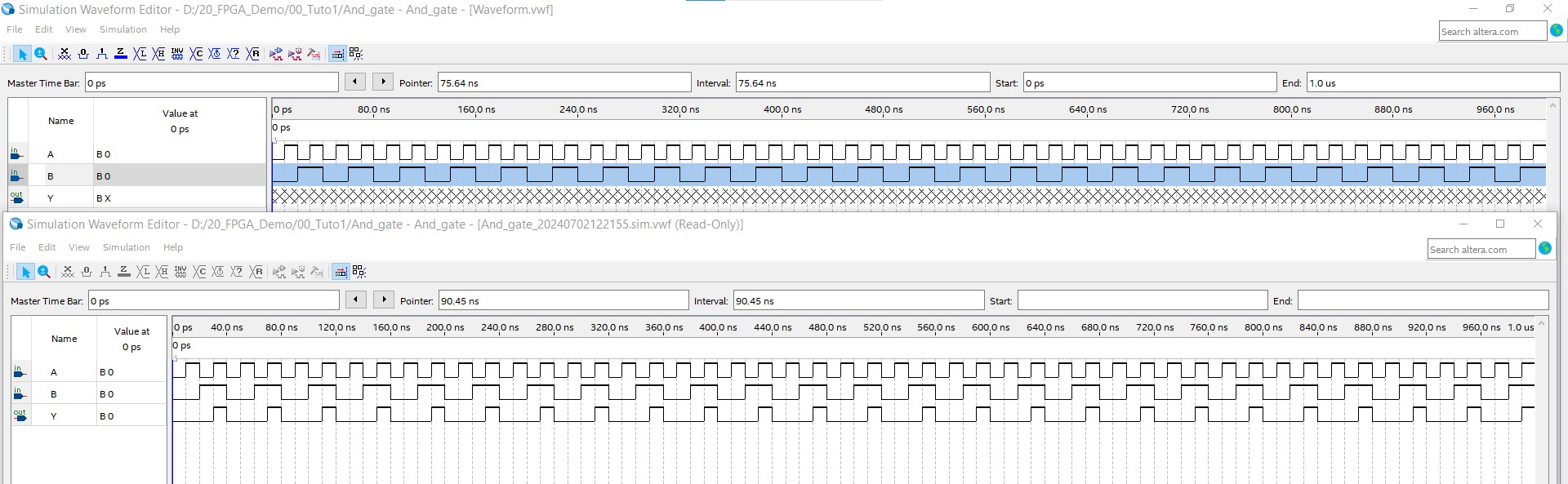
Waveform simulator
Since the design is very simple, I'll use the waveform simulator for now. This simulator is straightforward for small systems that use logic signals.
To run this simulation, you can add a waveform file to the project. You can list all the signals and drag them to the left side of the window. When selecting your signals, use the toolbar options for each input. Once you've finished selecting the waveforms, click on "RTL Simulation". A second window will appear with the simulation results.
Hardware test
First, you need to create the top-level file, which must have the same name as the design. If not, Quartus will generate an error and you will not be able to synthesize your design. Once the model and behavior are compiled without any errors, you can edit the pin assignments to connect the signals to the specified hardware pins. On my board, the push buttons are connected to specific pins, so we need to tell Quartus that each push button is used as an input and each LED is used as an output.

Once the pin assignments are done, you should click the compilation button again. Quartus will then compile the entire project.

When the compilation process is finished, you can flash the board and test your design.

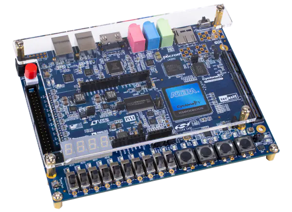
Test on Cyclone V board

Conclusion
This tutorial covered the basics of VHDL, including the structure of a VHDL file, the entity and architecture, and a basic example of an AND gate. You also learned how to write a testbench to simulate and verify the behavior of the AND gate.
🏷️ Author position : Embedded Software Engineer
🔗 Author LinkedIn : LinkedIn profile
Comments