Table of Contents
Modeling Combinational Components in VHDL
VHDL (VHSIC Hardware Description Language) is a powerful tool for modeling and simulating digital systems. One of the fundamental applications of VHDL is the modeling of combinational components, such as logic gates, multiplexers, and decoders. This article provides an overview of these combinational components, complete with examples and practical exercises to solidify understanding.
Logic Gates
Logic gates are the building blocks of digital circuits. VHDL allows us to model these gates using concurrent signal assignments and processes.
Example: AND Gate
An AND gate outputs a logic '1' only if all its inputs are '1'.
library IEEE;
use IEEE.STD_LOGIC_1164.ALL;

entity And_Gate is
    Port ( A : in  STD_LOGIC;
           B : in  STD_LOGIC;
           Y : out STD_LOGIC);
end And_Gate;

architecture Behavioral of And_Gate is
begin
    Y <= A and B;
end Behavioral;
Example: OR Gate
An OR gate outputs a logic '1' if at least one of its inputs is '1'.
library IEEE;
use IEEE.STD_LOGIC_1164.ALL;

entity Or_Gate is
    Port ( A : in  STD_LOGIC;
           B : in  STD_LOGIC;
           Y : out STD_LOGIC);
end Or_Gate;

architecture Behavioral of Or_Gate is
begin
    Y <= A or B;
end Behavioral;
Multiplexers
A multiplexer (MUX) selects one of several input signals and forwards the selected input to a single output line. The selection of the input is controlled by additional inputs known as select lines.
Example: 2-to-1 Multiplexer
A 2-to-1 multiplexer selects between two inputs.
library IEEE;
use IEEE.STD_LOGIC_1164.ALL;

entity Mux_2to1 is
    Port ( A : in  STD_LOGIC;
           B : in  STD_LOGIC;
           Sel : in  STD_LOGIC;
           Y : out STD_LOGIC);
end Mux_2to1;

architecture Behavioral of Mux_2to1 is
begin
    process (A, B, Sel)
    begin
        if (Sel = '0') then
            Y <= A;
        else
            Y <= B;
        end if;
    end process;
end Behavioral;
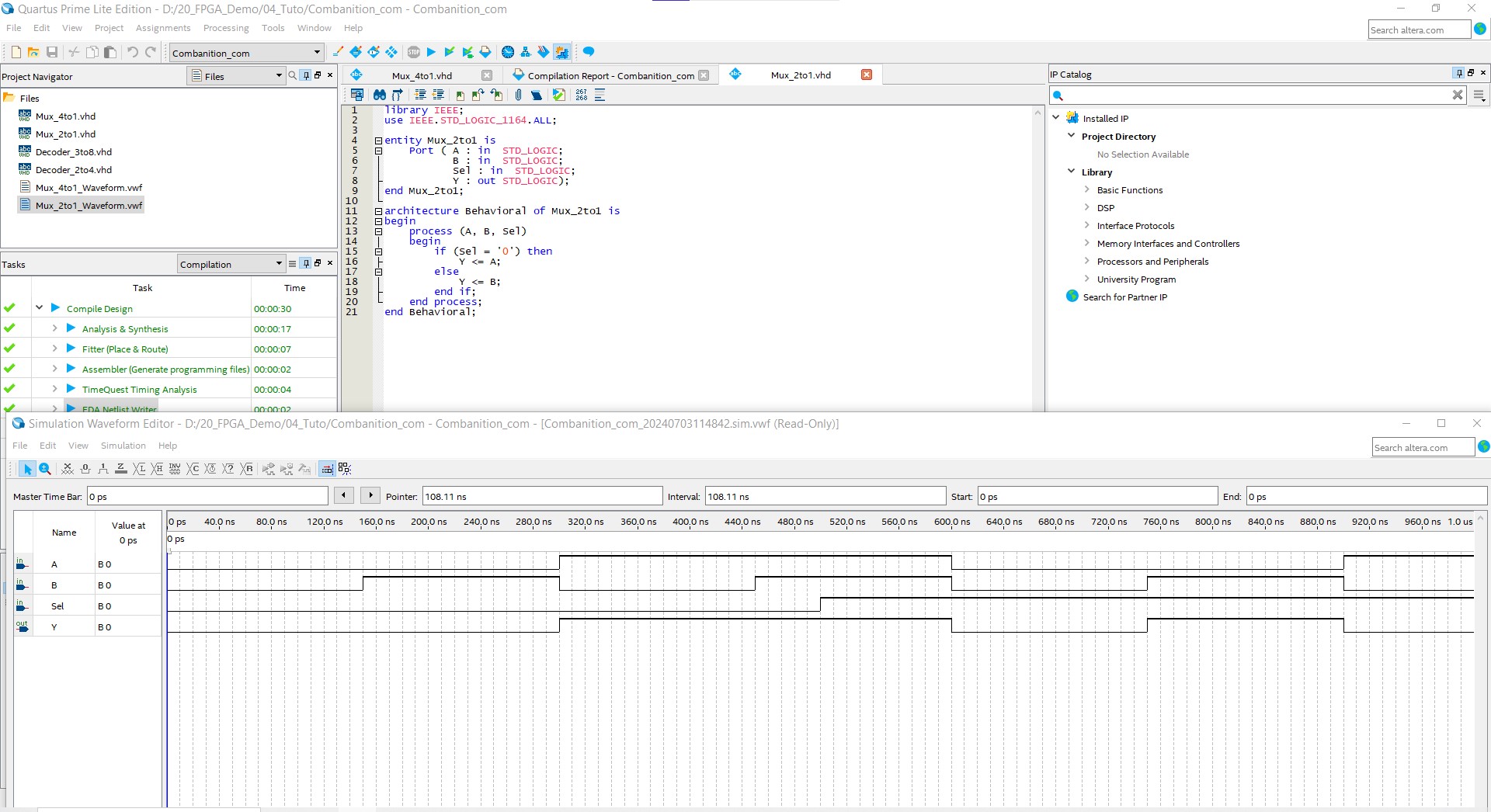
The figure below demonstrates the compilation process in Quartus and the simulation using a waveform simulator.

Decoders
A decoder converts binary information from n input lines to a maximum of 2^n unique output lines. It is often used in selecting among many devices.
Example: 2-to-4 Decoder
A 2-to-4 decoder has 2 inputs and 4 outputs.
library IEEE;
use IEEE.STD_LOGIC_1164.ALL;

entity Decoder_2to4 is
    Port ( A : in  STD_LOGIC_VECTOR (1 downto 0);
           Y : out STD_LOGIC_VECTOR (3 downto 0));
end Decoder_2to4;

architecture Behavioral of Decoder_2to4 is
begin
    process (A)
    begin
        case A is
            when "00" => Y <= "0001";
            when "01" => Y <= "0010";
            when "10" => Y <= "0100";
            when "11" => Y <= "1000";
            when others => Y <= "0000";
        end case;
    end process;
end Behavioral;
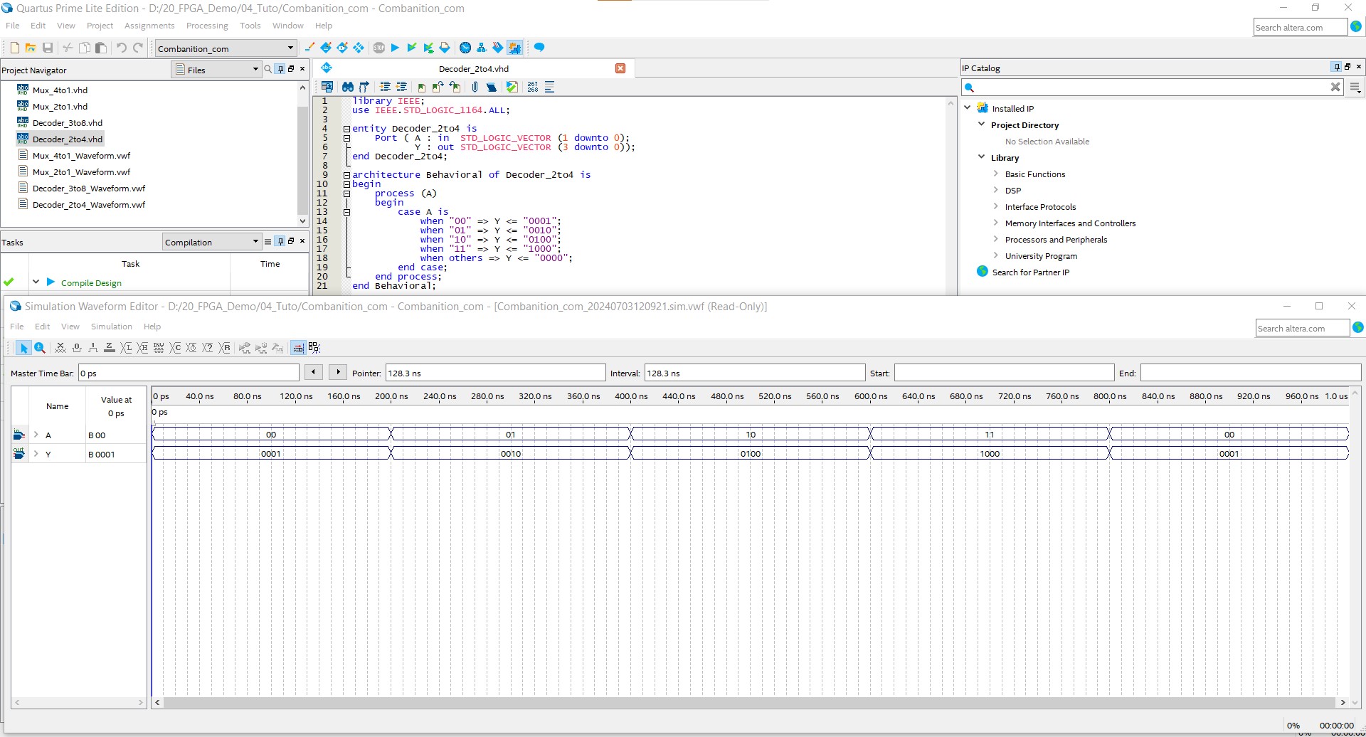
The figure below demonstrates the compilation process in Quartus and the simulation using a waveform simulator.

Practical Exercises
- Exercise: 4-to-1 Multiplexer
Create a 4-to-1 multiplexer in VHDL. The multiplexer should have 4 data inputs, 2 select inputs, and 1 output.
   library IEEE;
   use IEEE.STD_LOGIC_1164.ALL;

   entity Mux_4to1 is
       Port ( A : in  STD_LOGIC;
              B : in  STD_LOGIC;
              C : in  STD_LOGIC;
              D : in  STD_LOGIC;
              Sel : in  STD_LOGIC_VECTOR (1 downto 0);
              Y : out STD_LOGIC);
   end Mux_4to1;

   architecture Behavioral of Mux_4to1 is
   begin
       process (A, B, C, D, Sel)
       begin
           case Sel is
               when "00" => Y <= A;
               when "01" => Y <= B;
               when "10" => Y <= C;
               when "11" => Y <= D;
               when others => Y <= '0';
           end case;
       end process;
   end Behavioral;
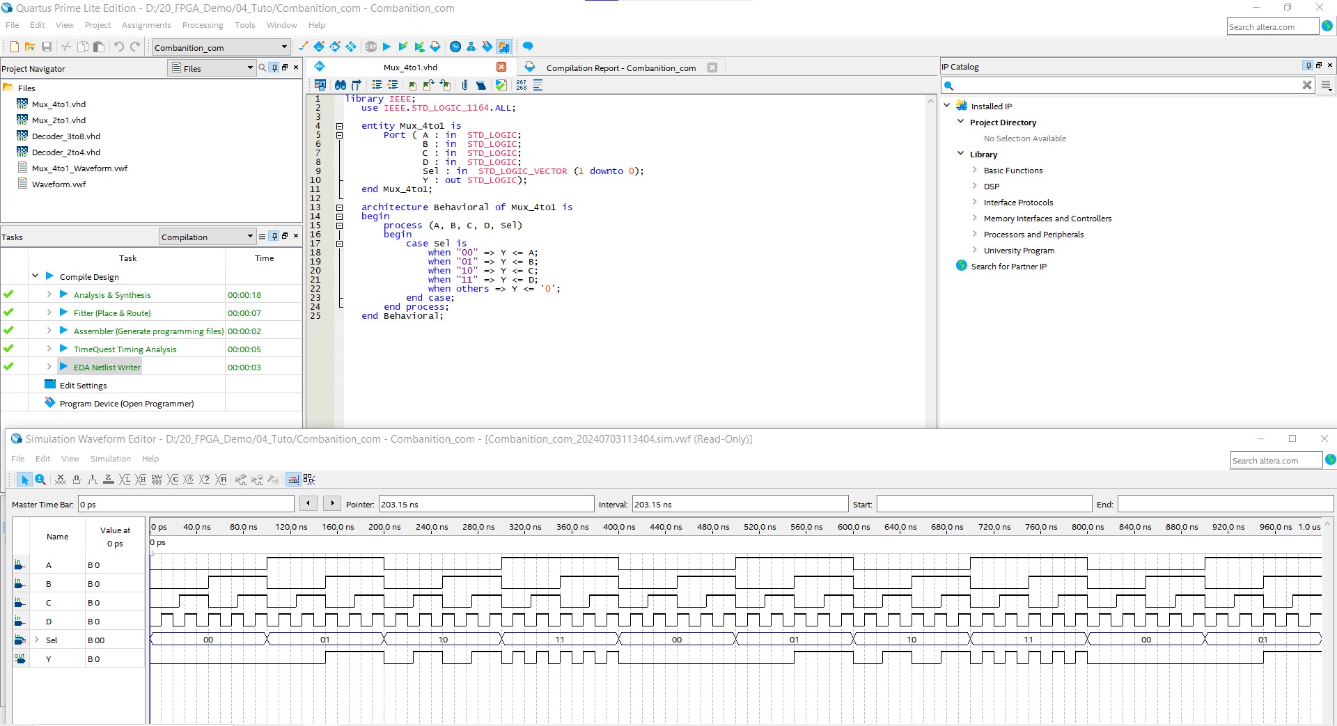
The figure below demonstrates the compilation process in Quartus and the simulation using a waveform simulator.

- Exercise: 3-to-8 Decoder
Design a 3-to-8 decoder in VHDL with 3 inputs and 8 outputs.
   library IEEE;
   use IEEE.STD_LOGIC_1164.ALL;

   entity Decoder_3to8 is
       Port ( A : in  STD_LOGIC_VECTOR (2 downto 0);
              Y : out STD_LOGIC_VECTOR (7 downto 0));
   end Decoder_3to8;

   architecture Behavioral of Decoder_3to8 is
   begin
       process (A)
       begin
           case A is
               when "000" => Y <= "00000001";
               when "001" => Y <= "00000010";
               when "010" => Y <= "00000100";
               when "011" => Y <= "00001000";
               when "100" => Y <= "00010000";
               when "101" => Y <= "00100000";
               when "110" => Y <= "01000000";
               when "111" => Y <= "10000000";
               when others => Y <= "00000000";
           end case;
       end process;
   end Behavioral;
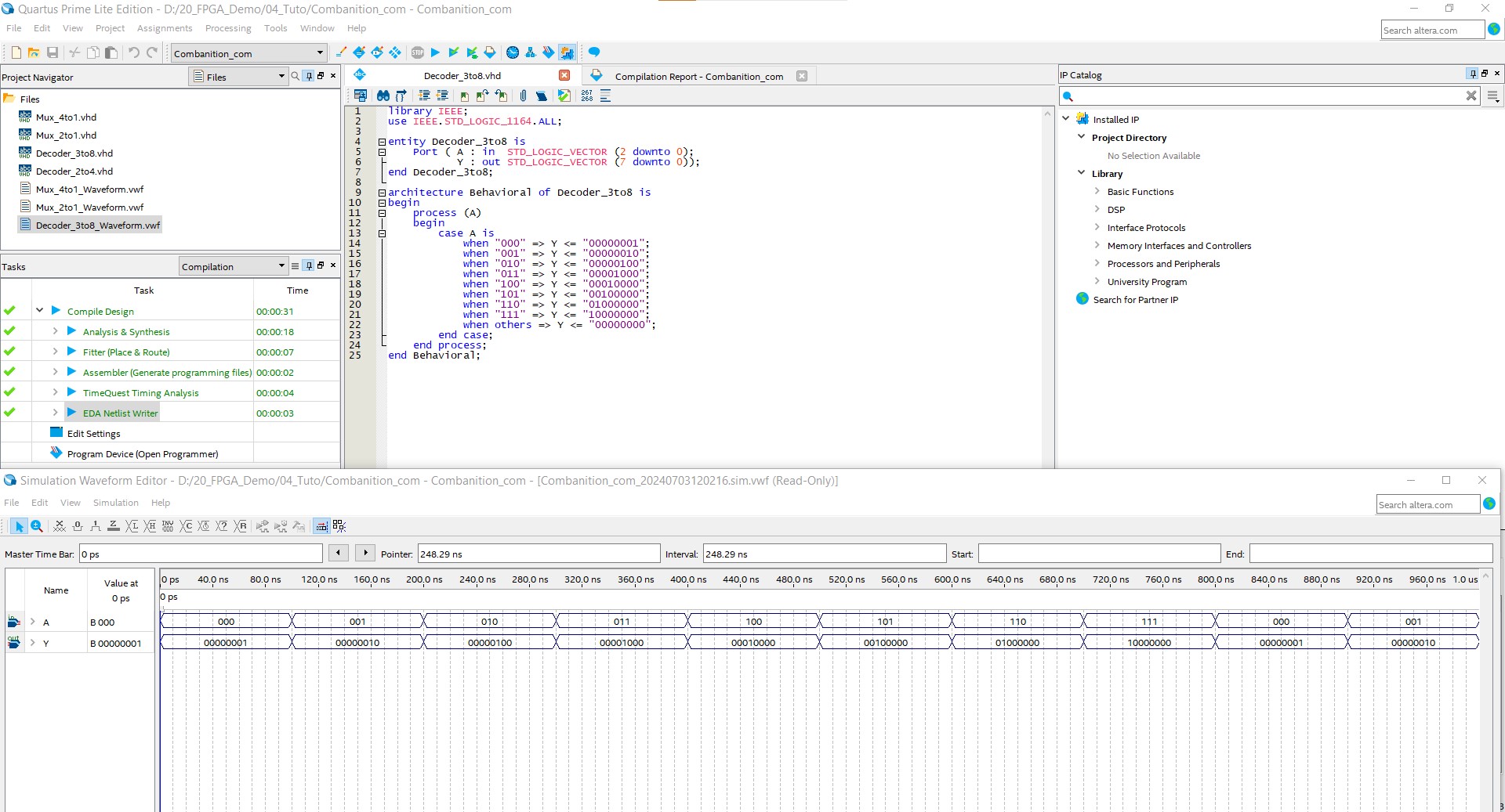
The figure below demonstrates the compilation process in Quartus and the simulation using a waveform simulator.

Conclusion
Modeling combinational components in VHDL is essential for creating efficient digital designs. Understanding how to implement logic gates, multiplexers, and decoders is fundamental for any digital designer. Through the provided examples and practical exercises, designers can gain hands-on experience in modeling these crucial components, thereby enhancing their VHDL proficiency.
🏷️ Author position : Embedded Software Engineer
🔗 Author LinkedIn : LinkedIn profile
Comments