Table of Contents
Modeling Sequential Components
Introduction
Sequential components are fundamental building blocks in digital circuits, enabling the storage, transfer, and synchronization of data. These components include flip-flops, registers, and counters, which are crucial for creating complex digital systems. This article explores these components and their implementation using VHDL's process statement.
Flip-Flops
Flip-flops are basic memory elements that store one bit of data. They are triggered by a clock signal, which allows them to change state. The most common types are the D (Data) flip-flop, T (Toggle) flip-flop, and JK flip-flop.
D Flip-Flop:
The D flip-flop stores the value of the data input (D) when a clock edge occurs.
library IEEE;
use IEEE.STD_LOGIC_1164.ALL;

entity D_flip_flop is
    Port ( D : in STD_LOGIC;
           CLK : in STD_LOGIC;
           Q : out STD_LOGIC);
end D_flip_flop;

architecture Behavioral of D_flip_flop is
begin
    process(CLK)
    begin
        if rising_edge(CLK) then
            Q <= D;
        end if;
    end process;
end Behavioral;
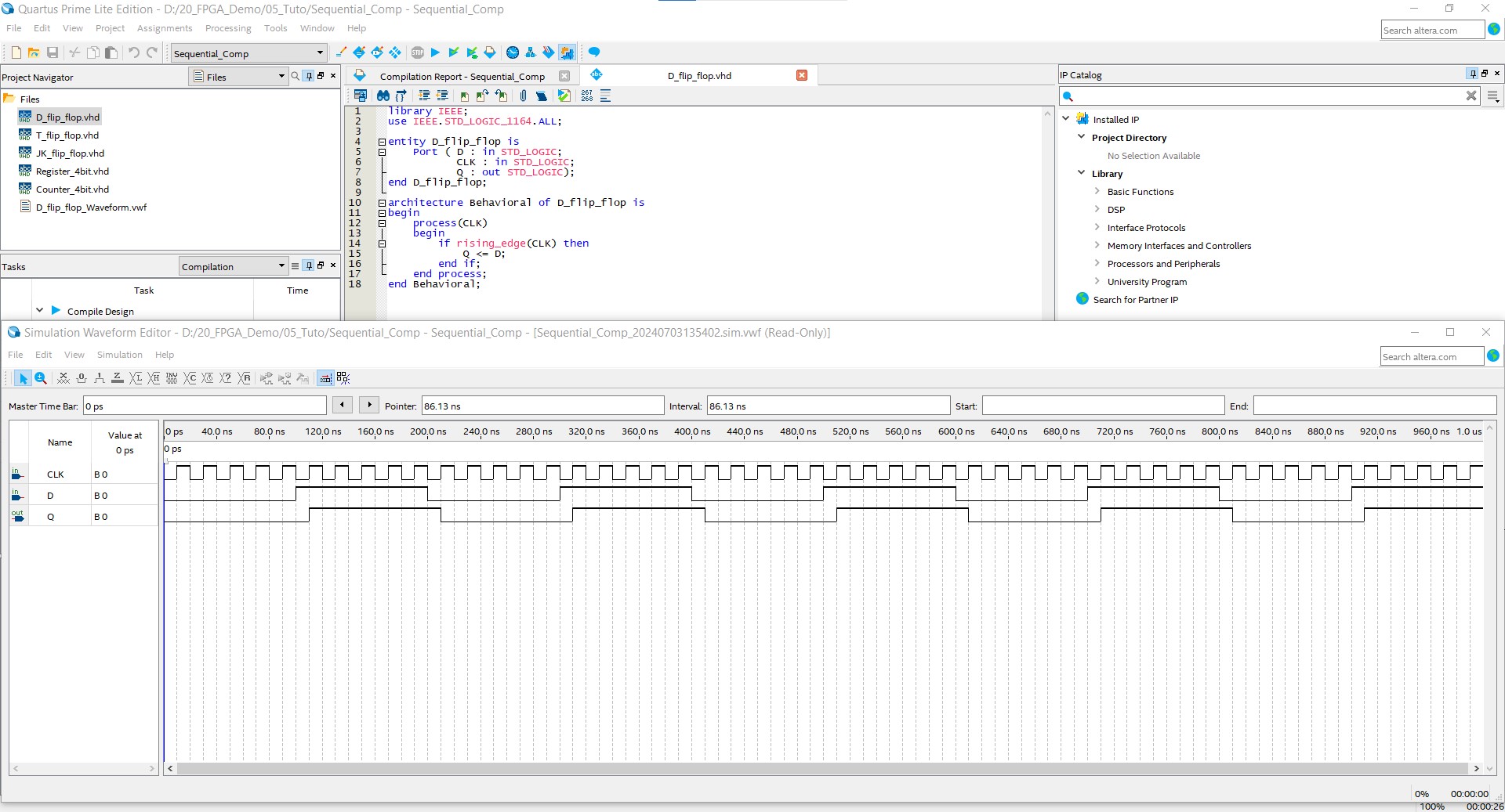
The figure below demonstrates the compilation process in Quartus and the simulation using a waveform simulator.
T Flip-Flop:
The T flip-flop toggles its state on each clock edge when the T input is high.
library IEEE;
use IEEE.STD_LOGIC_1164.ALL;

entity T_flip_flop is
    Port ( T : in STD_LOGIC;
           CLK : in STD_LOGIC;
           Q : out STD_LOGIC);
end T_flip_flop;

architecture Behavioral of T_flip_flop is
    signal Q_internal : STD_LOGIC := '0';
begin
    process(CLK)
    begin
        if rising_edge(CLK) then
            if T = '1' then
                Q_internal <= not Q_internal;
            end if;
        end if;
    end process;
    Q <= Q_internal;
end Behavioral;
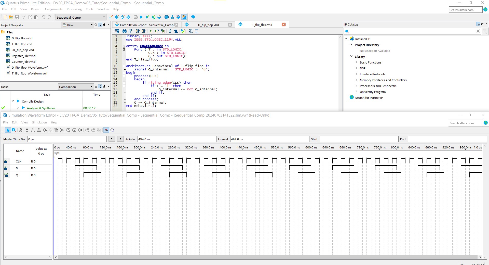
The figure below demonstrates the compilation process in Quartus and the simulation using a waveform simulator.
JK Flip-Flop:
The JK flip-flop can toggle, reset, or set its state depending on the values of the J and K inputs.
library IEEE;
use IEEE.STD_LOGIC_1164.ALL;

entity JK_flip_flop is
    Port ( J : in STD_LOGIC;
           K : in STD_LOGIC;
           CLK : in STD_LOGIC;
           Q : out STD_LOGIC);
end JK_flip_flop;

architecture Behavioral of JK_flip_flop is
    signal Q_internal : STD_LOGIC := '0';
    signal JK_vector : STD_LOGIC_VECTOR(1 downto 0);  -- Temporary signal for concatenation
begin
    process(CLK)
    begin
        if rising_edge(CLK) then
            JK_vector <= J & K;  -- Concatenate J and K
            case JK_vector is
                when "00" =>
                    Q_internal <= Q_internal;
                when "01" =>
                    Q_internal <= '0';
                when "10" =>
                    Q_internal <= '1';
                when "11" =>
                    Q_internal <= not Q_internal;
                when others =>
                    Q_internal <= Q_internal;
            end case;
        end if;
    end process;
    Q <= Q_internal;
end Behavioral;
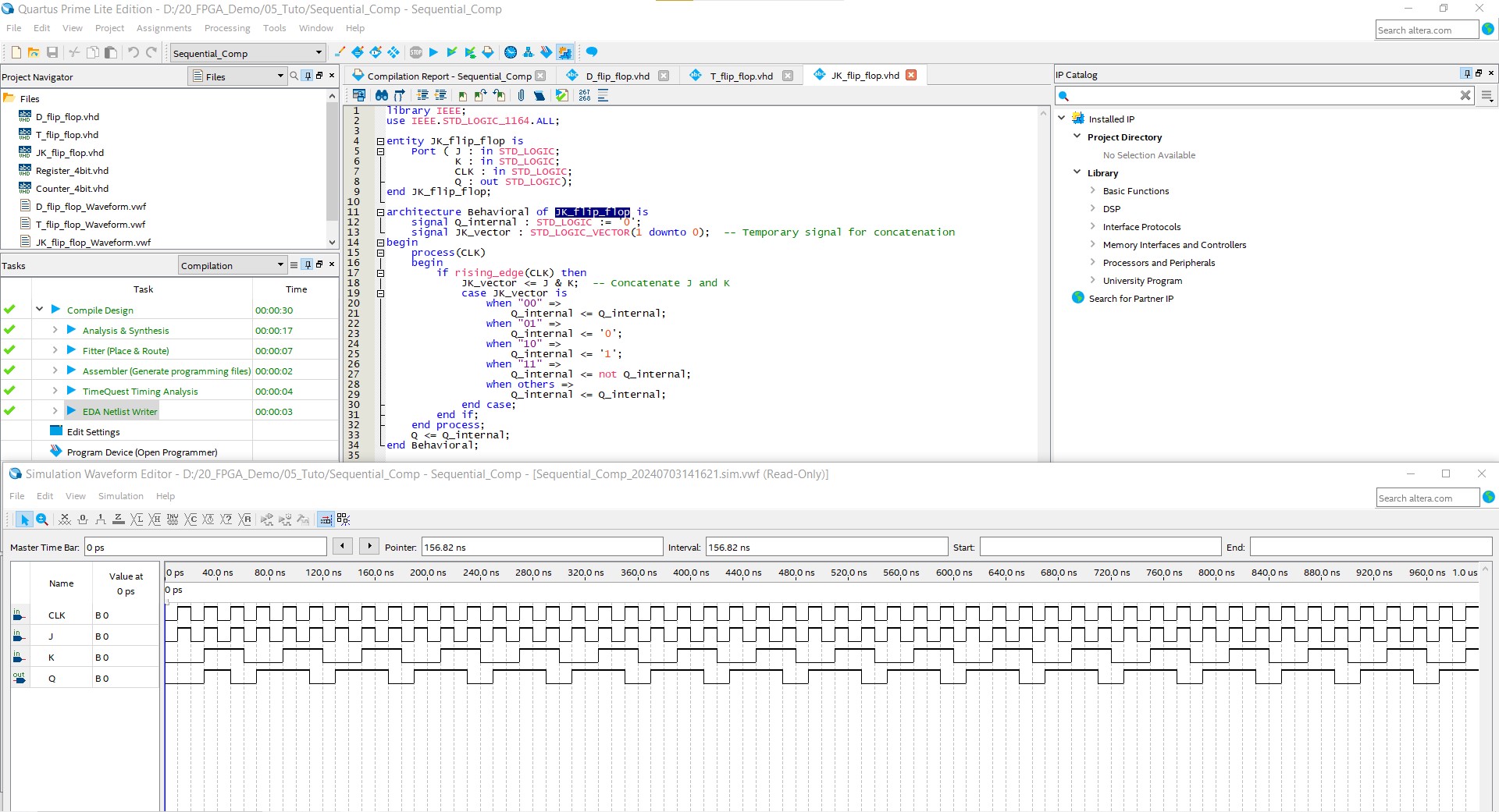
The figure below demonstrates the compilation process in Quartus and the simulation using a waveform simulator.
Registers
Registers are arrays of flip-flops used to store multiple bits of data. They can be implemented using D flip-flops and are often used to hold and transfer data in digital systems.
4-bit Register:
library IEEE;
use IEEE.STD_LOGIC_1164.ALL;

entity Register_4bit is
    Port ( D : in STD_LOGIC_VECTOR(3 downto 0);
           CLK : in STD_LOGIC;
           Q : out STD_LOGIC_VECTOR(3 downto 0));
end Register_4bit;

architecture Behavioral of Register_4bit is
    signal Q_internal : STD_LOGIC_VECTOR(3 downto 0) := (others => '0');
begin
    process(CLK)
    begin
        if rising_edge(CLK) then
            Q_internal <= D;
        end if;
    end process;
    Q <= Q_internal;
end Behavioral;
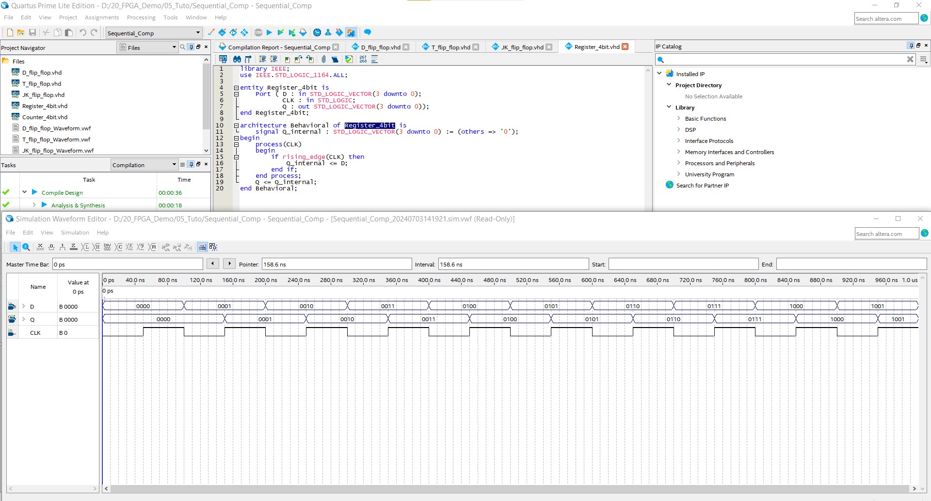
The figure below demonstrates the compilation process in Quartus and the simulation using a waveform simulator.
Counters
Counters are sequential circuits that go through a predefined sequence of states. They can be classified as synchronous or asynchronous based on their clocking scheme.
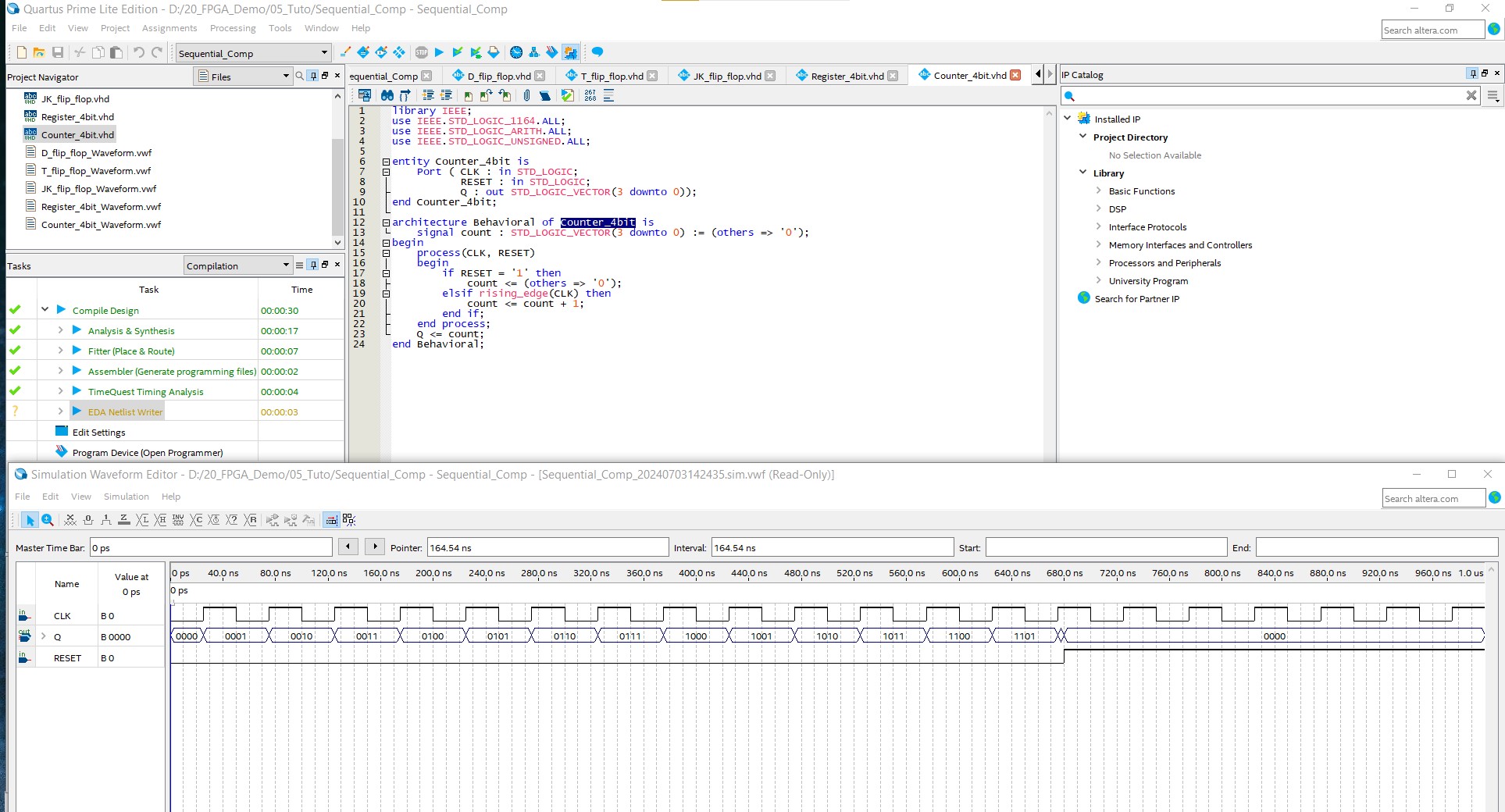
4-bit Synchronous Counter:
library IEEE;
use IEEE.STD_LOGIC_1164.ALL;
use IEEE.STD_LOGIC_ARITH.ALL;
use IEEE.STD_LOGIC_UNSIGNED.ALL;

entity Counter_4bit is
    Port ( CLK : in STD_LOGIC;
           RESET : in STD_LOGIC;
           Q : out STD_LOGIC_VECTOR(3 downto 0));
end Counter_4bit;

architecture Behavioral of Counter_4bit is
    signal count : STD_LOGIC_VECTOR(3 downto 0) := (others => '0');
begin
    process(CLK, RESET)
    begin
        if RESET = '1' then
            count <= (others => '0');
        elsif rising_edge(CLK) then
            count <= count + 1;
        end if;
    end process;
    Q <= count;
end Behavioral;
The figure below demonstrates the compilation process in Quartus and the simulation using a waveform simulator.
Using the Process Statement
The process statement in VHDL is a key construct for modeling sequential logic. It allows the description of behavior that depends on clock edges and enables the creation of flip-flops, registers, and counters.
- Sensitivity List: The process statement includes a sensitivity list that specifies signals that trigger the process.
- Sequential Statements: Inside a process, sequential statements (e.g., if, case) describe the desired behavior.
Example: D Flip-Flop using Process Statement
architecture Behavioral of D_flip_flop is
begin
    process(CLK)
    begin
        if rising_edge(CLK) then
            Q <= D;
        end if;
    end process;
end Behavioral;
Conclusion
Modeling sequential components like flip-flops, registers, and counters is fundamental in digital design. Using VHDL's process statement, designers can accurately describe the behavior of these components, ensuring proper functionality and timing in digital systems.
🏷️ Author position : Embedded Software Engineer
🔗 Author LinkedIn : LinkedIn profile
Comments