Table of Contents
Mastering State Machines in VHDL
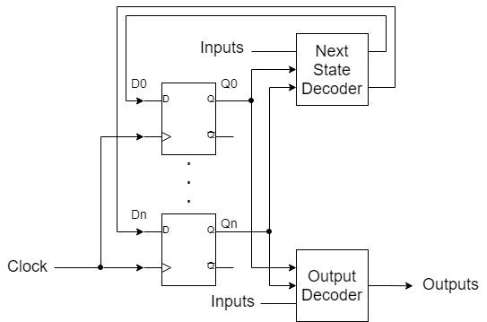
State machines are a fundamental concept in digital design, often used to manage the sequence of operations in a system. VHDL (VHSIC Hardware Description Language) is a powerful language that allows you to describe state machines concisely and effectively. In this article, we will explore the basics of state machines, how to implement them in VHDL, and provide example code and exercises to reinforce your understanding.
What is a State Machine?
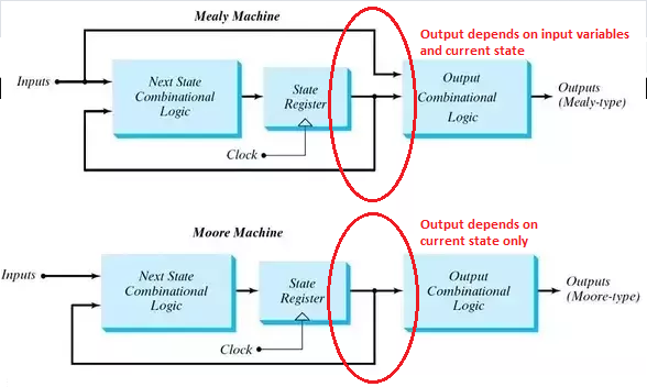
A state machine (or finite state machine, FSM) is a mathematical model of computation used to design both computer programs and sequential logic circuits. It consists of a finite number of states, transitions between these states, and actions. State machines can be classified into two types:
-
Moore State Machine:
Outputs depend only on the current state. -
Mealy State Machine:
Outputs depend on the current state and the current inputs.
Implementing State Machines in VHDL
To implement a state machine in VHDL, follow these steps:
- Define the states.
- Create a process for state transitions.
- Create a process for output logic.
Here are template VHDL codes for both Moore and Mealy state machines. These templates can be adapted to various applications by modifying the states, transitions, and outputs as needed.
Moore State Machine Template
In a Moore state machine, the outputs depend only on the current state. Here's a template VHDL code for a Moore state machine:
library IEEE;
use IEEE.STD_LOGIC_1164.ALL;
use IEEE.STD_LOGIC_ARITH.ALL;
use IEEE.STD_LOGIC_UNSIGNED.ALL;

entity moore_fsm is
    Port ( clk : in STD_LOGIC;
           reset : in STD_LOGIC;
           input_signal : in STD_LOGIC;
           output_signal : out STD_LOGIC);
end moore_fsm;

architecture Behavioral of moore_fsm is
    type state_type is (STATE1, STATE2, STATE3);
    signal state, next_state : state_type;
begin

    -- State transition process
    process(clk, reset)
    begin
        if reset = '1' then
            state <= STATE1;
        elsif rising_edge(clk) then
            state <= next_state;
        end if;
    end process;

    -- Next state logic
    process(state, input_signal)
    begin
        case state is
            when STATE1 =>
                if input_signal = '1' then
                    next_state <= STATE2;
                else
                    next_state <= STATE1;
                end if;
            when STATE2 =>
                if input_signal = '1' then
                    next_state <= STATE3;
                else
                    next_state <= STATE1;
                end if;
            when STATE3 =>
                next_state <= STATE1;
            when others =>
                next_state <= STATE1;
        end case;
    end process;

    -- Output logic (Moore machine: output depends only on state)
    process(state)
    begin
        case state is
            when STATE1 =>
                output_signal <= '0';
            when STATE2 =>
                output_signal <= '0';
            when STATE3 =>
                output_signal <= '1';
            when others =>
                output_signal <= '0';
        end case;
    end process;

end Behavioral;
Mealy State Machine Template
In a Mealy state machine, the outputs depend on both the current state and the current inputs. Here's a template VHDL code for a Mealy state machine:
library IEEE;
use IEEE.STD_LOGIC_1164.ALL;
use IEEE.STD_LOGIC_ARITH.ALL;
use IEEE.STD_LOGIC_UNSIGNED.ALL;

entity mealy_fsm is
    Port ( clk : in STD_LOGIC;
           reset : in STD_LOGIC;
           input_signal : in STD_LOGIC;
           output_signal : out STD_LOGIC);
end mealy_fsm;

architecture Behavioral of mealy_fsm is
    type state_type is (STATE1, STATE2, STATE3);
    signal state, next_state : state_type;
begin

    -- State transition process
    process(clk, reset)
    begin
        if reset = '1' then
            state <= STATE1;
        elsif rising_edge(clk) then
            state <= next_state;
        end if;
    end process;

    -- Next state logic
    process(state, input_signal)
    begin
        case state is
            when STATE1 =>
                if input_signal = '1' then
                    next_state <= STATE2;
                else
                    next_state <= STATE1;
                end if;
            when STATE2 =>
                if input_signal = '1' then
                    next_state <= STATE3;
                else
                    next_state <= STATE1;
                end if;
            when STATE3 =>
                next_state <= STATE1;
            when others =>
                next_state <= STATE1;
        end case;
    end process;

    -- Output logic (Mealy machine: output depends on state and input)
    process(state, input_signal)
    begin
        case state is
            when STATE1 =>
                output_signal <= '0';
            when STATE2 =>
                if input_signal = '1' then
                    output_signal <= '1';
                else
                    output_signal <= '0';
                end if;
            when STATE3 =>
                output_signal <= '1';
            when others =>
                output_signal <= '0';
        end case;
    end process;

end Behavioral;
How to Use These Templates
- Define States: Update the
state_typewith your specific states. - State Transitions: Modify the
next_statelogic to reflect the transitions based on your inputs and conditions. - Output Logic: For Moore machines, adjust the output logic based on states. For Mealy machines, adjust it based on both states and inputs.
These templates should serve as a starting point for implementing your own Moore and Mealy state machines in VHDL. Adjust the state types, transitions, and output logic to fit your specific design requirements.
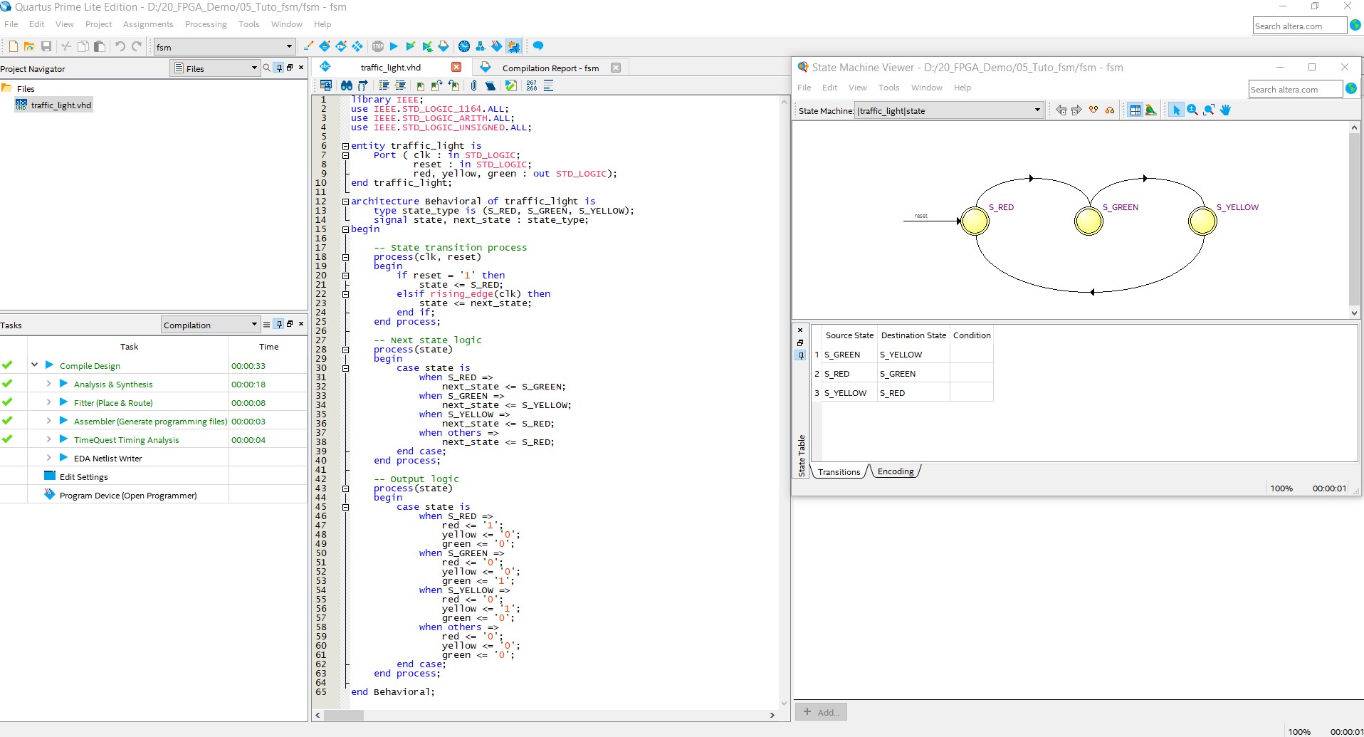
Here’s an example of a simple state machine implemented in VHDL. This example uses a Moore state machine to control a traffic light system.
Example: Traffic Light Controller
library IEEE;
use IEEE.STD_LOGIC_1164.ALL;
use IEEE.STD_LOGIC_ARITH.ALL;
use IEEE.STD_LOGIC_UNSIGNED.ALL;

entity traffic_light is
    Port ( clk : in STD_LOGIC;
           reset : in STD_LOGIC;
           red, yellow, green : out STD_LOGIC);
end traffic_light;

architecture Behavioral of traffic_light is
    type state_type is (S_RED, S_GREEN, S_YELLOW);
    signal state, next_state : state_type;
begin

    -- State transition process
    process(clk, reset)
    begin
        if reset = '1' then
            state <= S_RED;
        elsif rising_edge(clk) then
            state <= next_state;
        end if;
    end process;

    -- Next state logic
    process(state)
    begin
        case state is
            when S_RED =>
                next_state <= S_GREEN;
            when S_GREEN =>
                next_state <= S_YELLOW;
            when S_YELLOW =>
                next_state <= S_RED;
            when others =>
                next_state <= S_RED;
        end case;
    end process;

    -- Output logic
    process(state)
    begin
        case state is
            when S_RED =>
                red <= '1';
                yellow <= '0';
                green <= '0';
            when S_GREEN =>
                red <= '0';
                yellow <= '0';
                green <= '1';
            when S_YELLOW =>
                red <= '0';
                yellow <= '1';
                green <= '0';
            when others =>
                red <= '0';
                yellow <= '0';
                green <= '0';
        end case;
    end process;

end Behavioral;
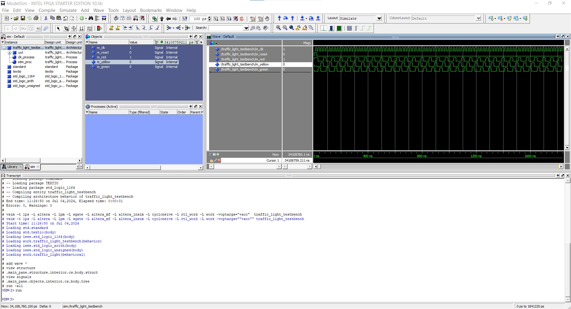
Example: Traffic Light Controller Test bench
LIBRARY ieee;
USE ieee.std_logic_1164.ALL;

ENTITY traffic_light_testbench IS
END traffic_light_testbench;

ARCHITECTURE behavior OF traffic_light_testbench IS

    COMPONENT traffic_light
    Port ( clk : in STD_LOGIC;
           reset : in STD_LOGIC;
           red, yellow, green : out STD_LOGIC);
    END COMPONENT;

    SIGNAL m_clk : std_logic := '0';
    SIGNAL m_reset : std_logic := '0';
    SIGNAL m_red, m_yellow, m_green : std_logic := '0';

BEGIN

    uut: traffic_light PORT MAP (
        clk => m_clk,
        reset => m_reset,
        red => m_red,
        yellow => m_yellow,
          green => m_green
    );

    clk_process :process
    begin
        m_clk <= '0';
        wait for 10 ns;
        m_clk <= '1';
        wait for 10 ns;
    end process;

    stim_proc: process
    begin
        m_reset <= '1';
        wait for 20 ns;
        m_reset <= '0';
        wait;
    end process;

END behavior;
Exercises
Modify the Traffic Light Controller:
- Add a pedestrian crossing signal that turns on a 'walk' signal when the traffic light is red.
- Ensure the pedestrian signal has appropriate timing.
@startuml
!define RECTANGLE class
skinparam class {
    BackgroundColor<<S_RED>> LightCoral
    BackgroundColor<<S_GREEN>> LightGreen
    BackgroundColor<<S_YELLOW>> LightYellow
}

RECTANGLE S_RED <<S_RED>> {
    * Red light ON
    * Yellow and Green lights OFF
    * Walk signal ON
    * Timer expires, transition to S_GREEN
}

RECTANGLE S_GREEN <<S_GREEN>> {
    * Green light ON
    * Red and Yellow lights OFF
    * Walk signal OFF
    * Timer expires, transition to S_YELLOW
}

RECTANGLE S_YELLOW <<S_YELLOW>> {
    * Yellow light ON
    * Red and Green lights OFF
    * Walk signal OFF
    * Timer expires, transition to S_RED
}

S_RED -down-> S_GREEN : Timer expires
S_GREEN -down-> S_YELLOW : Timer expires
S_YELLOW -down-> S_RED : Timer expires
@enduml
🔗Traffic light Solutionde VHDL code
🔗Traffic light Test Bench VHDL code
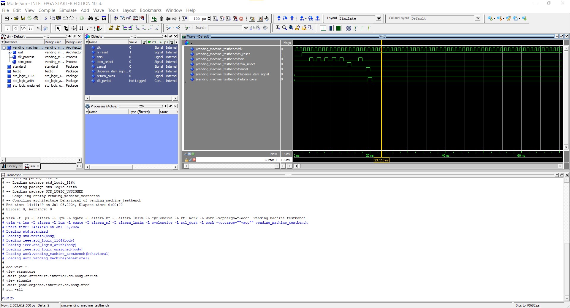
Design a Vending Machine Controller:
- Implement a state machine that controls a vending machine. The machine should accept coins, dispense an item, and provide change.
- States: IDLE, ACCEPTING_COINS, DISPENSE_ITEM, GIVE_CHANGE.
- Inputs: Coin (each coin adds to the total amount), Item_Select (selects the item), and Cancel (returns to IDLE).
- Outputs: Dispense_Item, Return_Coins.
@startuml
!define RECTANGLE class
skinparam class {
    BackgroundColor<<IDLE>> LightBlue
    BackgroundColor<<ACCEPTING_COINS>> LightGreen
    BackgroundColor<<DISPENSE_ITEM>> LightYellow
    BackgroundColor<<GIVE_CHANGE>> LightCoral
}

RECTANGLE IDLE <<IDLE>> {
    * Waiting for a coin to be inserted
    * If Cancel is pressed, remain in IDLE
}

RECTANGLE ACCEPTING_COINS <<ACCEPTING_COINS>> {
    * Continue accepting coins until an item is selected
    * If total amount >= item price, move to DISPENSE_ITEM
    * If Cancel is pressed, move to GIVE_CHANGE
}

RECTANGLE DISPENSE_ITEM <<DISPENSE_ITEM>> {
    * Dispense the selected item
    * After dispensing, move to GIVE_CHANGE if change is needed, otherwise move to IDLE
}

RECTANGLE GIVE_CHANGE <<GIVE_CHANGE>> {
    * Return the change
    * After returning change, move to IDLE
}

IDLE -down-> ACCEPTING_COINS : Coin inserted
ACCEPTING_COINS -down-> DISPENSE_ITEM : Total amount >= Item price
ACCEPTING_COINS -down-> GIVE_CHANGE : Cancel pressed
DISPENSE_ITEM -down-> GIVE_CHANGE : Dispense complete
GIVE_CHANGE -down-> IDLE : Change returned
ACCEPTING_COINS -right-> ACCEPTING_COINS : Coin inserted
@enduml
🔗Vending Machine Controller VHDL code
🔗Vending Machine Controller VHDL Test Bench code
Modelsime simulation
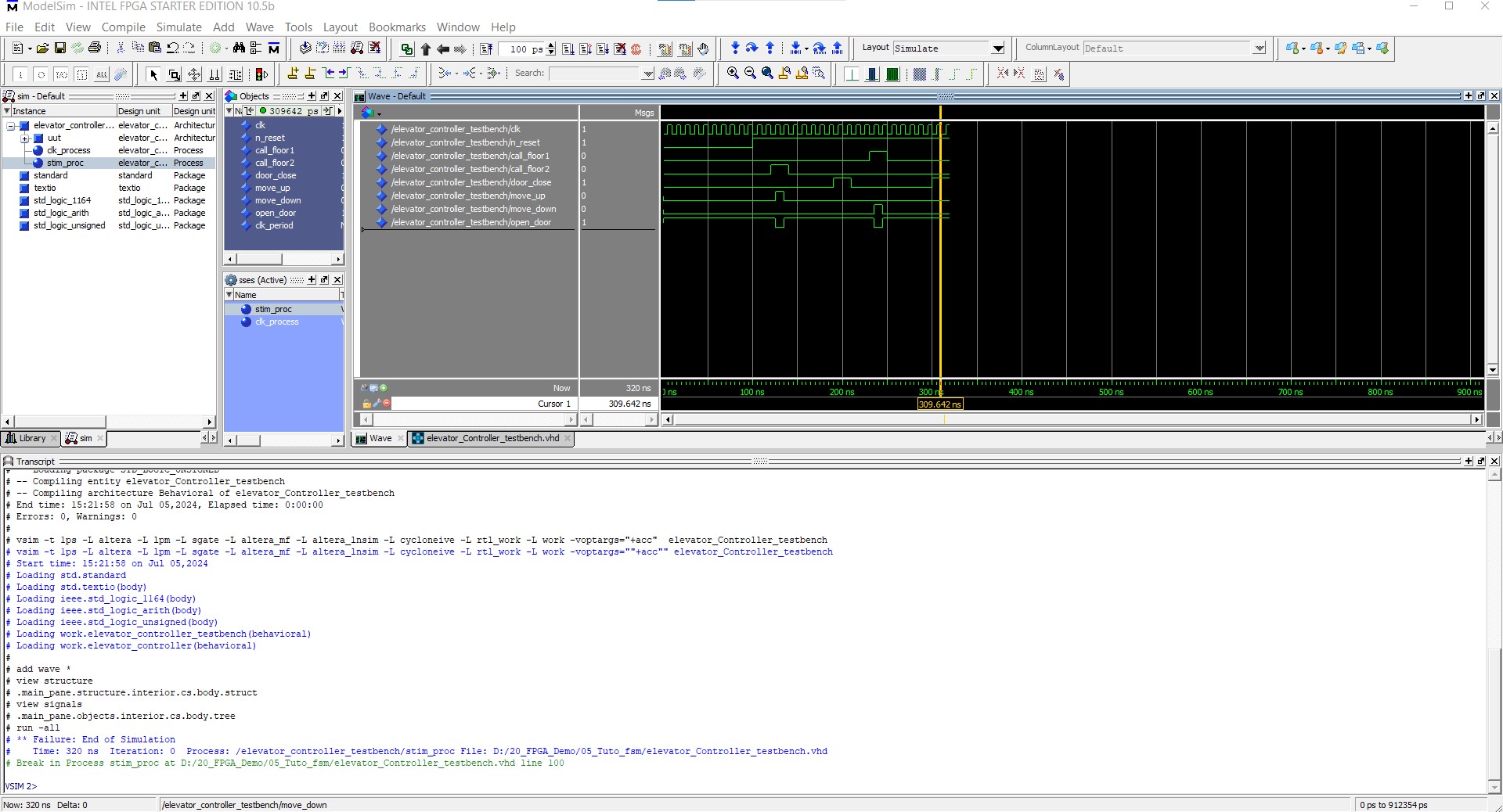
Elevator Controller:
- Design a state machine for a simple two-floor elevator.
- States: FLOOR1, FLOOR2, MOVING_UP, MOVING_DOWN.
- Inputs: Call_Floor1, Call_Floor2, Door_Close.
- Outputs: Move_Up, Move_Down, Open_Door.
@startuml
!define RECTANGLE class
skinparam class {
    BackgroundColor<<FLOOR1>> LightBlue
    BackgroundColor<<FLOOR2>> LightGreen
    BackgroundColor<<MOVING_UP>> LightYellow
    BackgroundColor<<MOVING_DOWN>> LightCoral
}

RECTANGLE FLOOR1 <<FLOOR1>> {
    * Elevator at Floor 1
    * Move_Up = 0, Move_Down = 0, Open_Door = 1
}

RECTANGLE FLOOR2 <<FLOOR2>> {
    * Elevator at Floor 2
    * Move_Up = 0, Move_Down = 0, Open_Door = 1
}

RECTANGLE MOVING_UP <<MOVING_UP>> {
    * Elevator moving up
    * Move_Up = 1, Move_Down = 0, Open_Door = 0
}

RECTANGLE MOVING_DOWN <<MOVING_DOWN>> {
    * Elevator moving down
    * Move_Up = 0, Move_Down = 1, Open_Door = 0
}

FLOOR1 -down-> MOVING_UP : Call_Floor2 and Door_Close
MOVING_UP -down-> FLOOR2 : Reached Floor 2
FLOOR2 -up-> MOVING_DOWN : Call_Floor1 and Door_Close
MOVING_DOWN -up-> FLOOR1 : Reached Floor 1

@enduml
🔗Elevator controller VHDL code
🔗Elevator control Test VHDL Bench code
Modelsime simulation
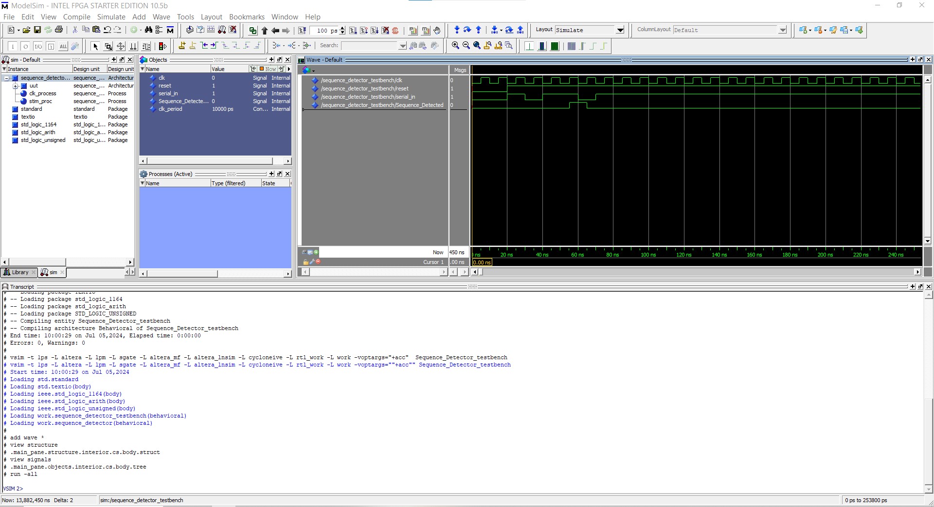
Sequence Detector:
- Create a state machine that detects a specific sequence of bits (e.g., 1011) in a serial input stream.
- Outputs: Sequence_Detected.
@startuml
!define RECTANGLE class
skinparam class {
    BackgroundColor<<IDLE>> LightBlue
    BackgroundColor<<S1>> LightGreen
    BackgroundColor<<S10>> LightYellow
    BackgroundColor<<S101>> LightCoral
    BackgroundColor<<S1011>> LightGray
}

RECTANGLE IDLE <<IDLE>> {
    * Waiting for first bit (1)
}

RECTANGLE S1 <<S1>> {
    * Detected 1
}

RECTANGLE S10 <<S10>> {
    * Detected 10
}

RECTANGLE S101 <<S101>> {
    * Detected 101
}

RECTANGLE S1011 <<S1011>> {
    * Detected 1011
    * Sequence_Detected = 1
}

IDLE -down-> S1 : 1
IDLE -down-> IDLE : 0

S1 -down-> S10 : 0
S1 -down-> S1 : 1

S10 -down-> S101 : 1
S10 -down-> IDLE : 0

S101 -down-> S1011 : 1
S101 -down-> S10 : 0

S1011 -down-> S1 : 1
S1011 -down-> IDLE : 0

@enduml
🔗Sequence Detector Test VHDL Bench code
Modelsime simulation
Conclusion
State machines are a vital part of digital design, enabling complex control logic to be broken down into manageable states and transitions. By practicing with VHDL and the examples provided, you can gain a deeper understanding of how to implement state machines effectively in your projects.
🏷️ Author position : Embedded Software Engineer
🔗 Author LinkedIn : LinkedIn profile
Comments