Table of Contents
1. VHDL Parameterized (Configuration on Altera/Intel Cyclone V in Quartus)
VHDL (VHSIC Hardware Description Language) is widely used for FPGA and ASIC design due to its flexibility and capability to describe complex digital circuits. Parameterized code generation in VHDL allows for the creation of versatile and reusable components by defining parameters that can be adjusted to meet specific design requirements. This is particularly useful when working with Altera (now Intel) Cyclone V FPGAs using the Quartus development environment. This article will provide an overview of how to generate and configure parameterized VHDL code for Cyclone V FPGAs in Quartus.
2. Parameterized Code in VHDL
Parameterized code in VHDL is achieved using generics. Generics allow you to pass parameters to a VHDL entity, making your code more flexible and reusable. Here’s an example of a simple VHDL module with generics:
library IEEE;
use IEEE.STD_LOGIC_1164.ALL;
use IEEE.NUMERIC_STD.ALL;

entity ParametrizedModule is
  generic (
    WIDTH : integer := 8
  );
  port (
    clk   : in  std_logic;
    reset : in  std_logic;
    data_in  : in  std_logic_vector(WIDTH-1 downto 0);
    data_out : out std_logic_vector(WIDTH-1 downto 0)
  );
end entity ParametrizedModule;

architecture Behavioral of ParametrizedModule is
begin
  process(clk, reset)
  begin
    if reset = '1' then
      data_out <= (others => '0');
    elsif rising_edge(clk) then
      data_out <= data_in;
    end if;
  end process;
end architecture Behavioral;
In this example, the WIDTH parameter defines the width of the data_in and data_out signals. This allows the same module to be instantiated with different data widths without modifying the code.
3. Configuring Parameterized VHDL in Quartus
3.1 Create a New Quartus Project
- Open Quartus and create a new project:
- Go to
File->New Project Wizard. - Follow the prompts to specify the project directory, name, and target device (Cyclone V).
3.2 Write the Parameterized VHDL Code
- In the Quartus project directory, create a new VHDL file (e.g.,
ParametrizedModule.vhd). - Write or paste the parameterized VHDL code into this file.
- Save the file.
3.2 Add the VHDL File to the Project
- In Quartus, add the VHDL file to the project:
- Go to
Project->Add/Remove Files in Project. - Add the
ParametrizedModule.vhdfile.
3.3 Instantiate the Parameterized Module
- Create a top-level VHDL file where you will instantiate the parameterized module.
- Instantiate the module with specific parameter values. For example:
library IEEE;
use IEEE.STD_LOGIC_1164.ALL;

entity TopLevel is
  port (
    clk   : in  std_logic;
    reset : in  std_logic;
    data_in  : in  std_logic_vector(15 downto 0);
    data_out : out std_logic_vector(15 downto 0)
  );
end entity TopLevel;

architecture Behavioral of TopLevel is
  signal data_out_internal : std_logic_vector(15 downto 0);
begin
  U1: entity work.ParametrizedModule
    generic map (
      WIDTH => 16
    )
    port map (
      clk => clk,
      reset => reset,
      data_in => data_in,
      data_out => data_out_internal
    );

  data_out <= data_out_internal;

end architecture Behavioral;
3.4 Compile the Project
- Save all files.
- Compile the project by clicking
Processing->Start Compilation.
3.5 Assign Pins
- Assign the FPGA pins to the top-level ports:
- Go to
Assignments->Pin Planner. - Assign the appropriate FPGA pins to
clk,reset,data_in, anddata_out.
3.6 Program the FPGA
- Connect your Cyclone V FPGA development board to your computer.
- Open the Programmer tool in Quartus:
- Go to
Tools->Programmer. - Add the compiled SOF file and program the FPGA.
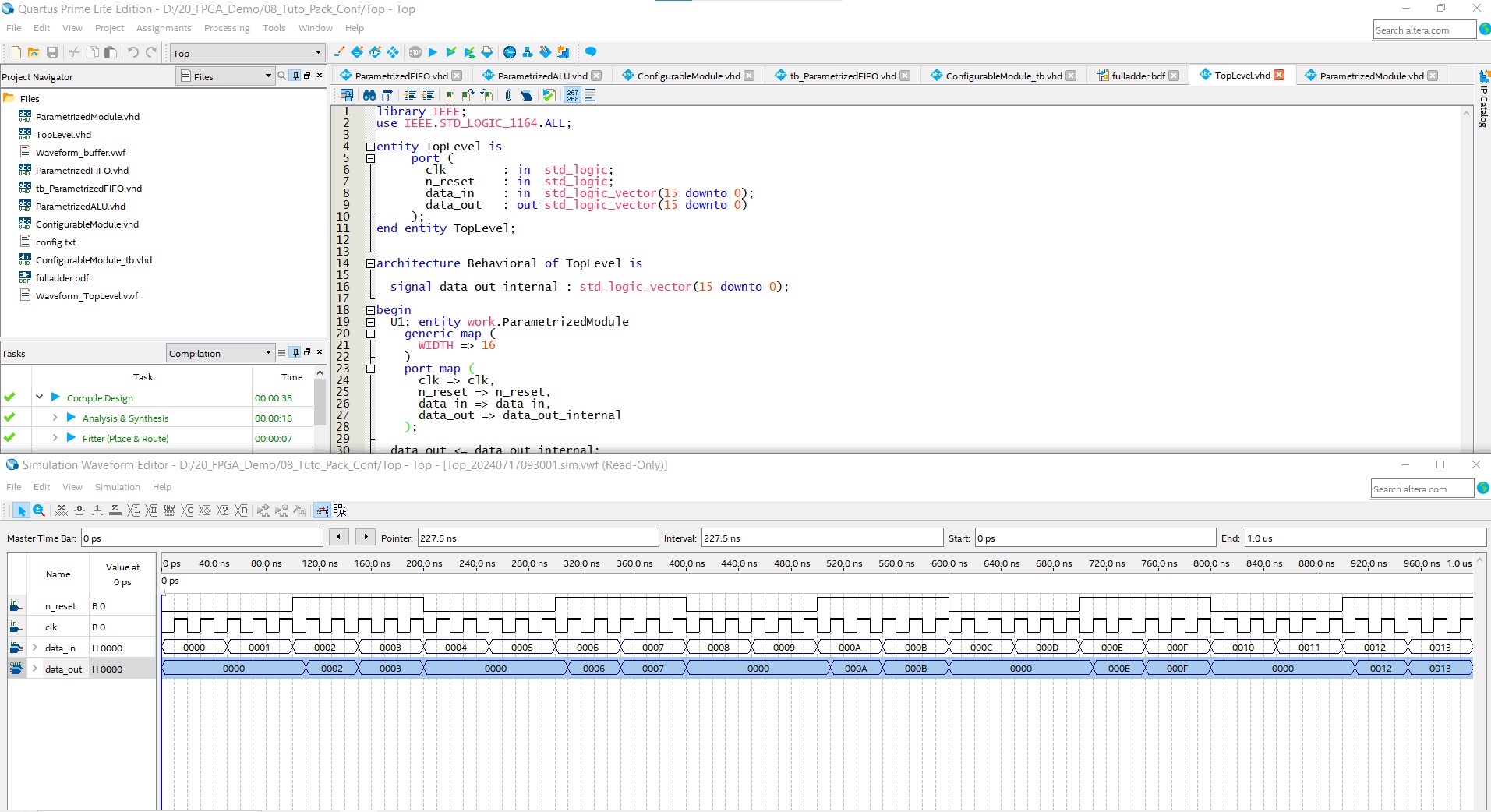
3.7 Using the simulation university waveforme

4. Using Block diagram / Schematic file
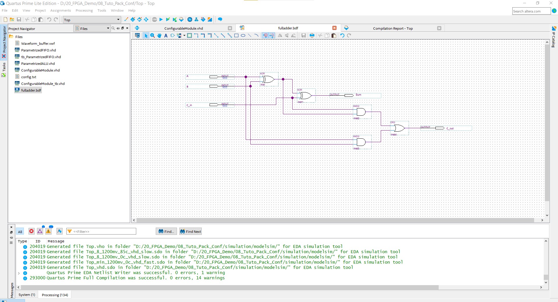
Quartus also enables us to create a VHDL model using schematics. Quartus compiles it and generates the VHDL code, which is not easily accessible. However, you can find it in the synthesis folder where Quartus generates the files.
This method is not very common or popular, but it does exist. Here is a picture of a full adder designed using the block diagram and schematic file.
Creating this schematic is very easy; you just need to open a new file and choose the Block Diagram / Schematic file option.

5. Advanced VHDL Configuration in Quartus for Cyclone V
5.1. Advanced Generics and Configurations
Example: Parameterized FIFO
A First-In-First-Out (FIFO) buffer is a common component that can benefit from advanced parameterization. Let's define a parameterized FIFO with generics for data width and depth.
library IEEE;
use IEEE.STD_LOGIC_1164.ALL;
use IEEE.NUMERIC_STD.ALL;

entity ParametrizedFIFO is
  generic (
    DATA_WIDTH : integer := 8;
    DEPTH      : integer := 16
  );
  port (
    clk     : in  std_logic;
    reset   : in  std_logic;
    wr_en   : in  std_logic;
    rd_en   : in  std_logic;
    data_in : in  std_logic_vector(DATA_WIDTH-1 downto 0);
    data_out: out std_logic_vector(DATA_WIDTH-1 downto 0);
    empty   : out std_logic;
    full    : out std_logic
  );
end entity ParametrizedFIFO;

architecture Behavioral of ParametrizedFIFO is
  type memory_type is array (0 to DEPTH-1) of std_logic_vector(DATA_WIDTH-1 downto 0);
  signal memory     : memory_type;
  signal wr_ptr     : integer range 0 to DEPTH-1 := 0;
  signal rd_ptr     : integer range 0 to DEPTH-1 := 0;
  signal fifo_count : integer range 0 to DEPTH := 0;
begin
  process(clk, reset)
  begin
    if reset = '1' then
      wr_ptr <= 0;
      rd_ptr <= 0;
      fifo_count <= 0;
    elsif rising_edge(clk) then
      if wr_en = '1' and fifo_count < DEPTH then
        memory(wr_ptr) <= data_in;
        wr_ptr <= (wr_ptr + 1) mod DEPTH;
        fifo_count <= fifo_count + 1;
      end if;
      if rd_en = '1' and fifo_count > 0 then
        data_out <= memory(rd_ptr);
        rd_ptr <= (rd_ptr + 1) mod DEPTH;
        fifo_count <= fifo_count - 1;
      end if;
    end if;
  end process;

  empty <= '1' when fifo_count = 0 else '0';
  full  <= '1' when fifo_count = DEPTH else '0';
end architecture Behavioral;
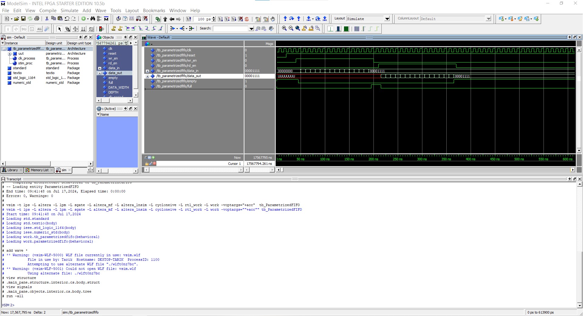
Example: Parameterized FIFO test bench
library IEEE;
use IEEE.STD_LOGIC_1164.ALL;
use IEEE.NUMERIC_STD.ALL;

entity tb_ParametrizedFIFO is
end entity tb_ParametrizedFIFO;

architecture Behavioral of tb_ParametrizedFIFO is
  constant DATA_WIDTH : integer := 8;
  constant DEPTH      : integer := 16;

  signal clk     : std_logic := '0';
  signal reset   : std_logic := '0';
  signal wr_en   : std_logic := '0';
  signal rd_en   : std_logic := '0';
  signal data_in : std_logic_vector(DATA_WIDTH-1 downto 0) := (others => '0');
  signal data_out: std_logic_vector(DATA_WIDTH-1 downto 0);
  signal empty   : std_logic;
  signal full    : std_logic;

  -- Clock period definition
  constant clk_period : time := 10 ns;

begin
  -- Instantiate the Unit Under Test (UUT)
  uut: entity work.ParametrizedFIFO
    generic map (
      DATA_WIDTH => DATA_WIDTH,
      DEPTH      => DEPTH
    )
    port map (
      clk     => clk,
      n_reset   => reset,
      wr_en   => wr_en,
      rd_en   => rd_en,
      data_in => data_in,
      data_out=> data_out,
      empty   => empty,
      full    => full
    );

  -- Clock process definitions
  clk_process : process
  begin
    clk <= '0';
    wait for clk_period/2;
    clk <= '1';
    wait for clk_period/2;
  end process;

  -- Stimulus process
  stim_proc: process
  begin
    -- Reset the FIFO
    reset <= '0';
    wait for clk_period*2;
    reset <= '1';
    wait for clk_period*2;

    -- Write to the FIFO
    for i in 0 to DEPTH-1 loop
      data_in <= std_logic_vector(to_unsigned(i, DATA_WIDTH));
      wr_en <= '1';
      wait for clk_period;
    end loop;
    wr_en <= '0';
    wait for clk_period;

    -- Read from the FIFO
    for i in 0 to DEPTH-1 loop
      rd_en <= '1';
      wait for clk_period;
    end loop;
    rd_en <= '0';
    wait for clk_period;

    -- Finish simulation
    wait;
  end process;

end architecture Behavioral;

6. Example: Using a Configuration File in VHDL
Let's create a VHDL model that reads configuration parameters from a text file.
6.1 Create a Configuration File
Create a text file named config.txt with the following content:
16
32
These two numbers will represent configuration parameters such as data width and depth for our VHDL model.
6.2 VHDL Model
Create a VHDL entity that uses these configuration parameters. The example below demonstrates a simple model that reads the parameters and uses them in a process.
6.2.1 Top-level VHDL File: ConfigurableModule.vhd
library IEEE;
use IEEE.STD_LOGIC_1164.ALL;
use IEEE.NUMERIC_STD.ALL;
use IEEE.STD_LOGIC_TEXTIO.ALL;
use STD.TEXTIO.ALL;

entity ConfigurableModule is
  port (
    clk   : in  std_logic;
    reset : in  std_logic;
    data_in  : in  std_logic_vector(15 downto 0);
    data_out : out std_logic_vector(15 downto 0)
  );
end entity ConfigurableModule;

architecture Behavioral of ConfigurableModule is
  constant FILE_NAME : string := "config.txt";
  signal data_width : integer;
  signal depth : integer;
  type memory_type is array (0 to depth-1) of std_logic_vector(data_width-1 downto 0);
  signal memory : memory_type;
  signal wr_ptr : integer := 0;
begin

  process(clk, reset)
    file config_file : text open read_mode is FILE_NAME;
    variable line_content : line;
    variable width, depth_var : integer;
  begin
    if reset = '1' then
      data_out <= (others => '0');
    elsif rising_edge(clk) then
      if endfile(config_file) = false then
        readline(config_file, line_content);
        read(line_content, width);
        readline(config_file, line_content);
        read(line_content, depth_var);
        data_width <= width;
        depth <= depth_var;
      end if;
      -- Example usage of data_width and depth
      if wr_ptr < depth then
        memory(wr_ptr) <= data_in;
        wr_ptr <= wr_ptr + 1;
      end if;
      data_out <= memory(wr_ptr - 1);
    end if;
  end process;
end architecture Behavioral;
6.3 Explanation
- Configuration File:
config.txtcontains two integers representing the data width and depth. - Entity and Architecture: The entity
ConfigurableModulehas standardclk,reset,data_in, anddata_outports. - Process for Reading the File:
- Use the
textiolibrary to read from the file. - Open the file
config.txtin read mode. - Read each line and convert it to an integer.
- Assign the values to
data_widthanddepth. - Usage: The
data_widthanddepthparameters are then used within the process to create a memory buffer and manage writing and reading operations.
6.4 Simulation
This model can be simulated using a VHDL simulator like ModelSim or GHDL. The simulator will read the configuration file and apply the parameters during simulation.
6.4.1 Steps for Simulation in ModelSim
-
Compile the VHDL File:
sh vcom ConfigurableModule.vhd -
Simulate the Model:
sh vsim work.ConfigurableModule -
Run the Simulation:
sh
   run -all
7. Conclusion
Using a file for VHDL configuration, leveraging the textio library for dynamic parameterization, enhances the flexibility, reusability, and adaptability of designs, particularly in simulation and testing, while advanced configuration techniques ensure efficient and scalable digital systems in FPGA development.
🏷️ Author position : Embedded Software Engineer
🔗 Author LinkedIn : LinkedIn profile
Comments