Table of Contents

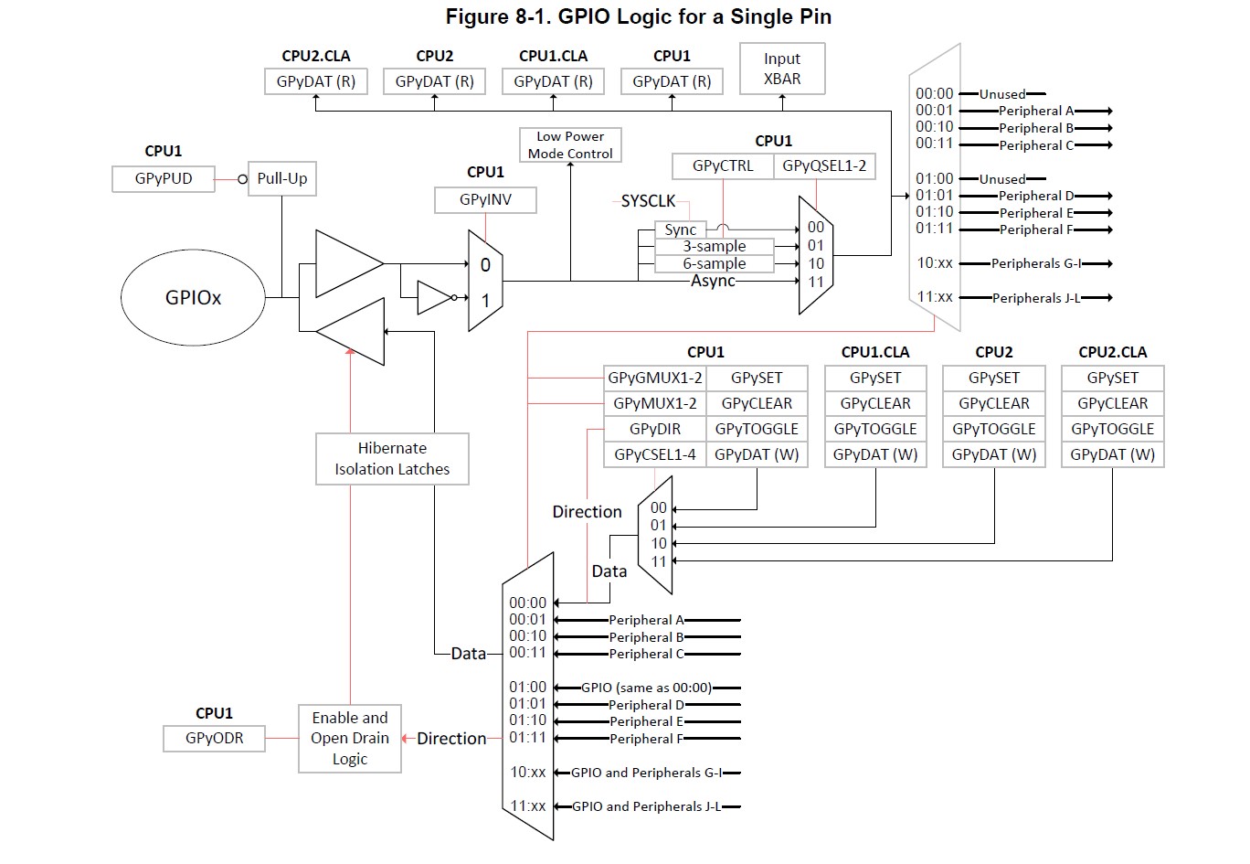
One Pin diagram connection with CPUs, other peripherals and CLAs
In this article I'll outlining the steps to set, reset, and toggle a GPIO on the Texas Instruments TMS320F28379D DSP. This article includes a sample C code that you can import into Code Composer Studio (CCS) for testing.
How to Set, Reset, and Toggle GPIO on TMS320F28377D DSP
Introduction
The TMS320F28377D DSP from Texas Instruments is part of the C2000 series of real-time controllers, often used for power electronics, motor control, and industrial automation applications. Controlling GPIO pins on this DSP is essential for interfacing with other devices, such as sensors, indicators, and communication modules.
In this guide, we’ll go over:
- Setting up the GPIO for output.
- Setting and resetting a GPIO pin.
- Toggling a GPIO pin.
Prerequisites
- Texas Instruments Code Composer Studio (CCS)
- A TMS320F28377D development board
- Basic knowledge of embedded C programming
Step 1: Configuring the GPIO Pin
First, let’s initialize and configure the GPIO pin as an output. This setup ensures the pin is correctly configured to send signals.
In this example, we’ll use GPIO0 as the target pin.
Code Walkthrough
Here’s a step-by-step breakdown of the C code.
1. Setting Up the GPIO for Output
To use GPIO0, configure it as an output pin and enable it in the GPADIR (GPIO A Direction) register.
#include "F28x_Project.h"  // Device Header File

void InitGpioPin(void)
{
    EALLOW;                      // Enable protected register access

    GpioCtrlRegs.GPAMUX1.bit.GPIO0 = 0; // Set GPIO0 as GPIO (not another peripheral function)
    GpioCtrlRegs.GPADIR.bit.GPIO0 = 1;  // Set GPIO0 as output

    EDIS;                        // Disable protected register access
}
This code does the following:
- Enables access to protected registers with
EALLOW. - Configures
GPAMUX1register to ensure that GPIO0 is set as a general-purpose IO (not assigned to any other peripheral). - Sets the direction of GPIO0 as output by setting the
GPADIRregister. - Disables access to protected registers with
EDIS.
2. Setting and Resetting the GPIO Pin
To set or reset the GPIO pin, we use GPASET and GPACLEAR registers, respectively.
void SetGpioPin(void)
{
    GpioDataRegs.GPASET.bit.GPIO0 = 1; // Set GPIO0 (output high)
}

void ResetGpioPin(void)
{
    GpioDataRegs.GPACLEAR.bit.GPIO0 = 1; // Clear GPIO0 (output low)
}
Here:
GPASET.bit.GPIO0 = 1;sets GPIO0 to high.GPACLEAR.bit.GPIO0 = 1;resets GPIO0 to low.
3. Toggling the GPIO Pin
To toggle the GPIO, we use the GPATOGGLE register. This register inverts the current state of the specified GPIO pin.
void ToggleGpioPin(void)
{
    GpioDataRegs.GPATOGGLE.bit.GPIO0 = 1; // Toggle GPIO0
}
- Each call to
GPATOGGLEchanges GPIO0 from high to low or low to high.
Full Code Example
Here’s the complete example, which includes initializing, setting, resetting, and toggling GPIO0 on the TMS320F28377D.
#include "F28x_Project.h"  // Device Header File

void InitGpioPin(void)
{
    EALLOW;
    GpioCtrlRegs.GPAMUX1.bit.GPIO0 = 0; // GPIO functionality
    GpioCtrlRegs.GPADIR.bit.GPIO0 = 1;  // GPIO0 as output
    EDIS;
}

void SetGpioPin(void)
{
    GpioDataRegs.GPASET.bit.GPIO0 = 1; // Set GPIO0 high
}

void ResetGpioPin(void)
{
    GpioDataRegs.GPACLEAR.bit.GPIO0 = 1; // Set GPIO0 low
}

void ToggleGpioPin(void)
{
    GpioDataRegs.GPATOGGLE.bit.GPIO0 = 1; // Toggle GPIO0
}

int main(void)
{
    InitSysCtrl();    // Initialize the system control
    InitGpioPin();    // Initialize GPIO0 for output

    while(1)
    {
        SetGpioPin();     // Set GPIO0 high
        DELAY_US(1000000); // 1-second delay

        ResetGpioPin();   // Set GPIO0 low
        DELAY_US(1000000); // 1-second delay

        ToggleGpioPin();  // Toggle GPIO0
        DELAY_US(1000000); // 1-second delay
    }
}
Explanation
InitSysCtrl()initializes the system control. Make sure to include any necessary system setup here.InitGpioPin()configures GPIO0 as an output.- Inside the
while(1)loop: SetGpioPin()sets GPIO0 high.ResetGpioPin()sets GPIO0 low.ToggleGpioPin()inverts GPIO0's current state.DELAY_US(1000000)introduces a delay of 1 second (1000000 microseconds) between actions for visibility in testing.
Importing and Testing in Code Composer Studio (CCS)
- Open Code Composer Studio.
- Create a new project targeting the TMS320F28377D.
- Copy this code into the main C file of your project.
- Build and load the code onto your TMS320F28377D development board.
- Run the code and observe GPIO0 toggling with a 1-second delay between states.
Conclusion
This guide demonstrated how to set, reset, and toggle a GPIO pin on the TMS320F28377D DSP. By configuring the GPIO as an output and using the respective registers, you can control external components effectively.
🏷️ Author position : Senior Embedded Software Engineer
🔗 Author LinkedIn : LinkedIn profile
Comments